Introduction to Components With LittleBits
Hands-on IoT with - Littlebits Intro
Cybersecurity First Principles in this lesson
-
Abstraction: An abstraction is a representation of an object or concept. It could be something such as a door, a speedometer, or a data structure in computer science. Abstraction decouples the design from the implementation. The gauges in an automobile are an abstraction of the performance of a car. A map is an abstraction of the earth.
-
Modularization: The concept of modularity is like building blocks. Each block (or module) can be put in or taken out from a bigger project. Each module has its own separate function that is interchangeable with other modules.
-
Simplicity: Simplicity allows a person to better understand hardware and software. Without the clutter of unnecessarily complicated code and interfaces, the software will be more understandable by people that will update the code when requirements change. It will be easier to understand by the testers and they will be able to spot problems sooner. By keeping software as simple and as focused as possible, the reliability and security is greatly increased.
Introduction
In this lesson, we will explore a cool hands-on technology called Littlebits. Littlebits follows a component-based design paradigm using GPIO (or general purpose input/output) to let you easily make apps. We will learn how to plug and play bits together to make some simple inventions. Littlebits will be the central platform for the rest of camp and you will be using them in other lessons.
Goals
By the end of this tutorial, you will be able to:
- Use Littlebits and GPIO to make your first (or another) IoT app
- Understand IoT
modularity - Come up with some of your own app ideas
Materials Required
- Littlebits kit
- Power outlet nearby
Prerequisite lessons
None
Table of Contents
- Hands-on IoT with - Littlebits Intro
- Cybersecurity First Principles in this lesson
- Introduction
- Goals
- Materials Required
- Prerequisite lessons
- Table of Contents
- Step 1: Unbox it!
- Step 2: Gotta start somewhere
- Step 3: Count all the things!
- Step 4: The world is more than True or False - Variable Inputs
- Step 5: Hey, Listen - Audio
- Step 6: Turning on an outlet with the IR transmitter
- Step 7: Motoring onward
- Self Exploration
- Test Your Bits, err… Wits!
- Additional Resources
- Acknowledgements
- License
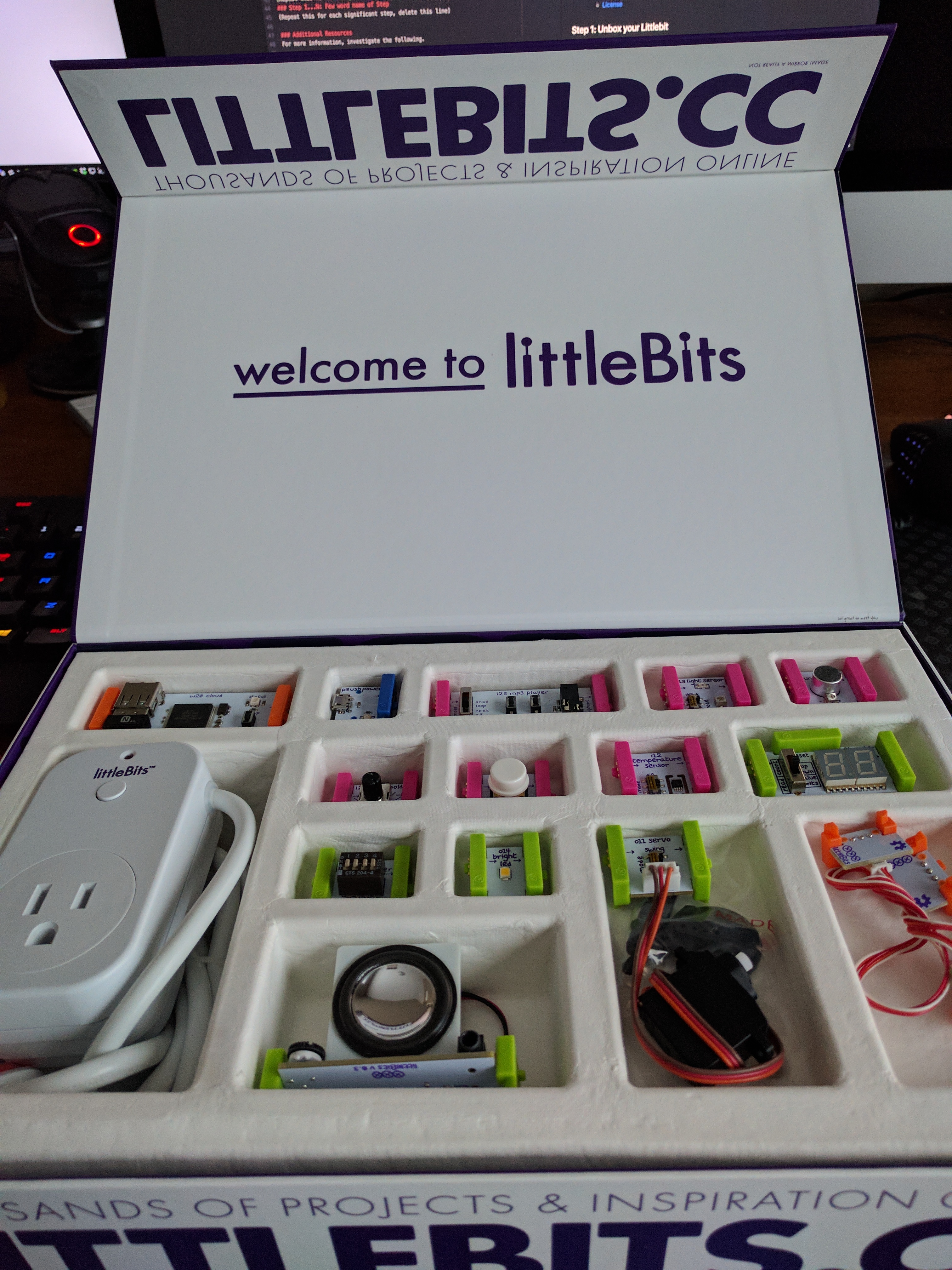
Step 1: Unbox it!
First, open your Littlebits box. Take a second to look at the different components you have. Littlebits is organized around three colors:
- Pink modules are inputs, like an On/Off button.
- Green modules are outputs, like LEDs and Fans.
- Orange modules are special and usually are supportive - think splitters and logic handlers.
- Blue modules are power related.
Look over each module. Your box should include a helpful component diagram fold-out poster that shows off each of your modules. Read about some of them.
Step 2: Gotta start somewhere
No time like the present. Lets make a simple invention:
- find the blue
powermodule. - find the pink
buttoninput module - find the green
bright ledoutput module
Lets make a simple circuit:
- Connect the power to the wall
- Connect micro USB end to the
powermodule - Connect the
buttonto thepowermodule - Connect the
bright ledto thebutton.
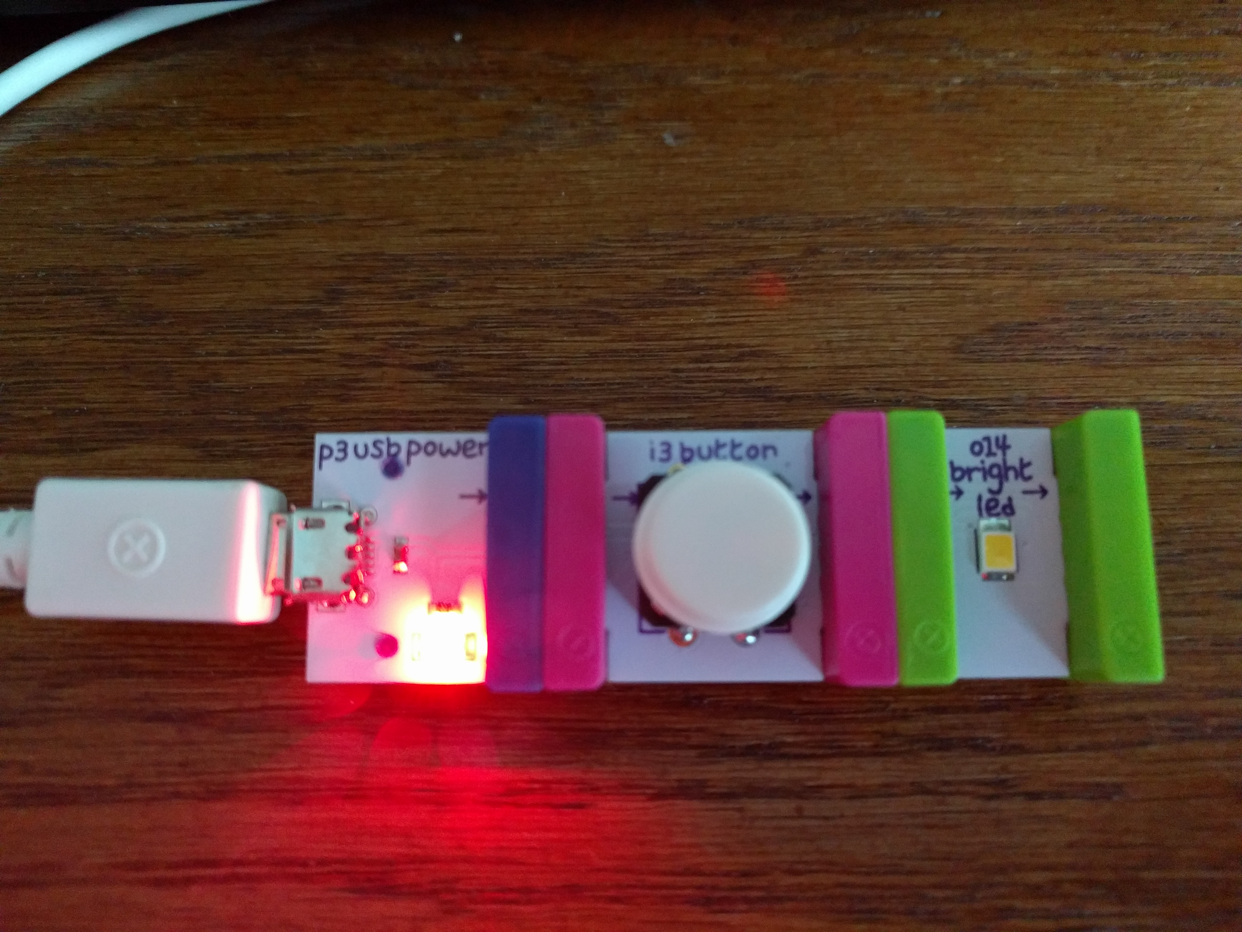
Press the button and the light turns on. That was easy!
This is GPIO in a nutshell. Each module has a general purpose input and output, with a standard interface, and doesn’t need to understand or know anything about what they are connected to. These modules also need to protect themselves from invalid input. This is a great example of the modularity cybersecurity first principle.
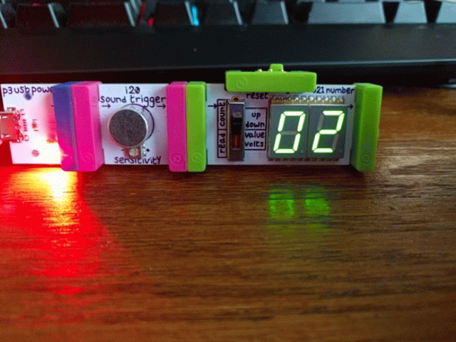
Step 3: Count all the things!
Ok, we’ve made our first circuit - but it’s pretty simple. Let’s add some more modules:
- Find the green
o21 numberoutput module
Time to extend your previous circuit to 
- Connect the
o21 numberto thebright led - Set the switch to the up position on the
o21 numbermodule. This puts it into count mode instead of voltage mode.
Press the button!
Pretty simple. Notice we can chain the output modules together (bright led and a counter in this case). Any number of output modules can be chained together.
Now, lets switch up our circuit a bit.
- Find the pink
sound triggerinput module - Find the pink
light sensorinput module
Lets swap some components around.
- Remove the
bright ledmodule (it is really bright!)
Press the button. Everything still works!
- Connect the
light sensorto thepowerand then to thebutton
Press the button. Does it work? How about if you cover up the light sensor?
This shows you that you can also chain multiple input modules together and their total behavior is a combination of their input designs. In this case, our counter only worked if the light was detected AND the button was pressed.
Lets try one more combo:
- Remove the
buttonmodule. - Remove the
light sensormodule. - Connect the
sound triggerbetween thepowerand theo21 numbermodule.
Snap your fingers or tap the table near your device.
Step 4: The world is more than True or False - Variable Inputs
So far, we have outputs and inputs that result in an on (True) or off (False) behavior.
 .
.
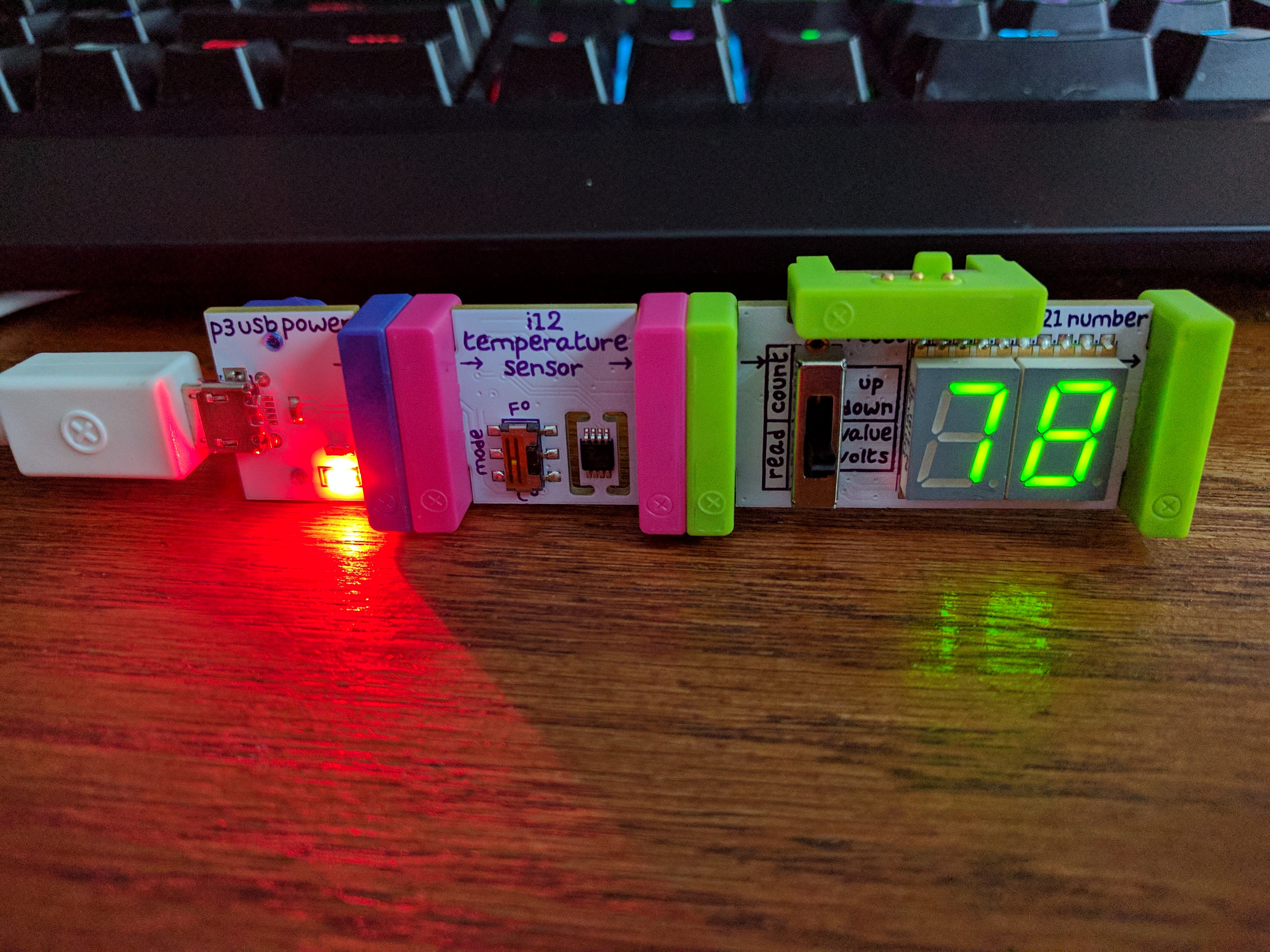
The world is not always on or off
- Find the pink
temperature sensorinput module. - Find the pink
i23 thresholdinput module. - Get the
light sensorandbright ledout again
We are going to make a circuit that shows off variable voltage.
- Remove all components.
- Connect the
temperature sensorto theo21 numbermodule. - Set the
o21 numberswitch to value (middle position) - Set the
temperature sensorswitch to f (for Fahrenheit)
You should see the current temperature in the room near the device.
- Replace the
temperature sensorwith thelight sensor - Put the
o21 numbermodule back into voltage mode by moving the switch to the bottom position. - Move your finger closer to and further away from the light sensor
You should see that the more light it gets, the more voltage it outputs.
- Now connect the
bright ledto the right-hand side of theo21 numbermodule - Move your finger closer to and further away from the light sensor
You should notice the light dimming and brightening depending on the voltage it receives.
Ok, last part!
- Connect the
i23 thresholdmodule between theo21 numberandbright ledmodules - Set the threshold on the
i23 thresholdby turning the knob. - Keep turning until a voltage of roughly 3 or greater turns on the
bright led - You can put your finger over the light sensor to change the voltage
So, what did we learn? The thresholder can set a voltage tolerance and output a 1 (True) if its input is greater than the threshold*. This can be helpful if you want to do sound, light, or temperature detection, but you only want to output True if the value is greater than some value.
Step 5: Hey, Listen - Audio

Photo Credit: CmOrigins@deviantart http://cmorigins.deviantart.com/art/Navi-Hey-Listen-322389835
Sometimes you want your inventions to have some sound. The next design we will explore involves using audio.
- Find the pink
mp3 playerinput module - Find the green
synth speakeroutput module - Get the pink
buttonmodule again
Lets play a sound when a button is pressed:
- Remove all components
- Connect the
buttonto thepower - Connect the
mp3 playerto thebutton - Connect the
synth speakerto themp3 player
Press the button. This plays all of the tracks. If you move the mp3 player switch to next, it will allow you to press the button to switch tracks. You can also use the buttons on the mp3 player board.
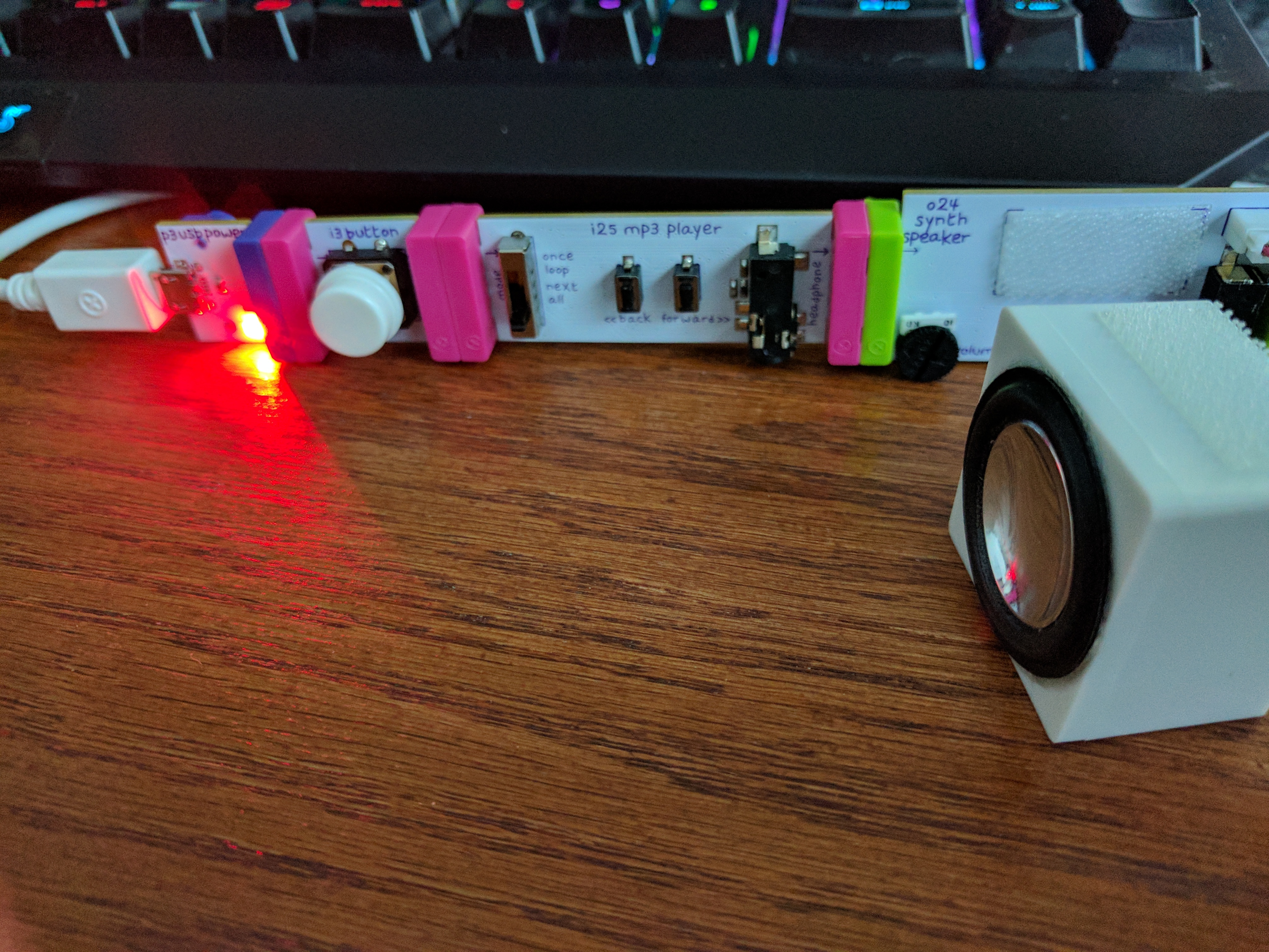
By default, the mp3 player comes loaded with stock Littlebits tutorial audio. You can replace it using the sdcard in the board to load it with your own audio.
Step 6: Turning on an outlet with the IR transmitter
The next module to explore is the ir transmitter and power outlet combo.
- Find the green
ir transmitteroutput module - Find the outlet with IR sensor (hard to miss)
- Get your pink
buttonmodule
Lets wire this up so that when you press the button the outlet comes on.
- Remove all components
- Connect the
buttonup to thepower - Plug the outlet into a nearby power outlet
- Plug something up to the outlet (optional)
- Connect the
ir transmitterto thebutton
Pressing the button should turn on the device. The first time you press it, you will see the outlet light blink. It is pairing up. Once its paired, press the button a few times. You can see the red light turn on and off as you do.
Note: Since it is IR, the IR transmitter needs line-of-sight to the IR sensor on the outlet.
Step 7: Motoring onward
The last module we will explore is the servo which can bring actual movement into your inventions!
- Remove all components
- Connect the
buttonto thepower. - Connect the
servoto thebutton. - Open the packet of black attachments and pick one of the arms.
- Attach the arm by pushing it down onto the
white plastic gearon theservo - Set the switch on the
servoboard toturn.
Note you don’t need to use the screw, but hang onto it for later - it should be used in production to secure the turner down
When you press the button, it should rotate the arm 90 degrees.
This can be used for all kinds of purposes!
Self Exploration
Try some different designs yourself.
Test Your Bits, err… Wits!
Additional Resources
For more information, investigate the following:
- Littlebits - Overview of concepts and available bits
- https://shop.littlebits.cc/products/smart-home-kit - Information about the Smart Home Kit
Acknowledgements
Special thanks to Dr. Robin Gandhi for reviewing and editing this lesson.
License
Nebraska GenCyber 
is licensed under a Creative Commons Attribution-NonCommercial-ShareAlike 4.0 International License.
Overall content: Copyright (C) 2017-2018 Dr. Matthew L. Hale, Dr. Robin Gandhi, and Doug Rausch.
Lesson content: Copyright (C) Dr. Matthew L. Hale 2017-2018.
This lesson is licensed by the author under a Creative Commons Attribution-NonCommercial-ShareAlike 4.0 International License.